ShopNotes No. 8 has an article on making a very nice sliding bevel gauge from brass and hardwood. It looks like it will be a beautiful tool when completed. I decided to use walnut. An appropriate scrap was available and the article recommends a dark wood as sanding brass will stain a lighter wood.

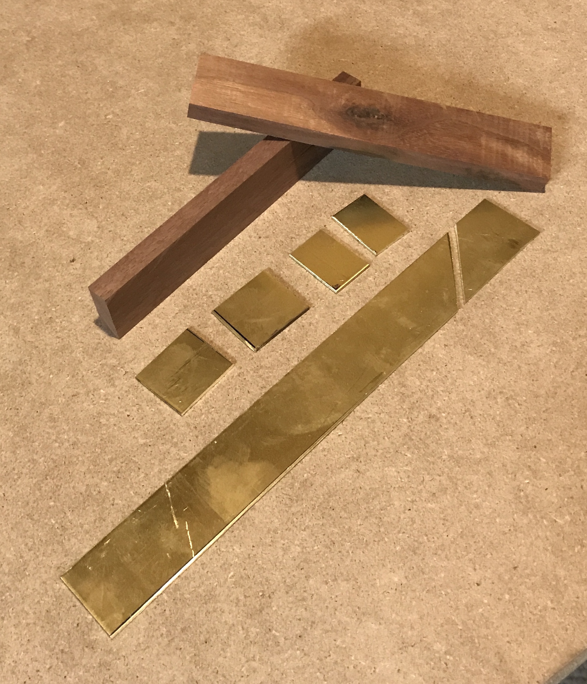
A large sheet of 1/16" brass was cut to make the brass parts. First, a 1" wide strip was cut from the sheet with a hacksaw. The sheet was clamped flat on the table saw to make this cut, which had to be made from both ends. This strip was deburred with the belt sander. Two 1" long pieces were cut from the strip followed by two 3/4" pieces. A 45° angle was cut across the remaining strip 3/4" from one end. This produced the last two brass parts, including the knife. All parts were deburred with the belt sander as they had some pretty nasty burrs.
The walnut piece was cut to length, 5 3/4". 1" wide strips were cut from this blank and these were then thinned to 3/8", all on the table saw. The resulting brass and walnut parts are shown in the photo below.
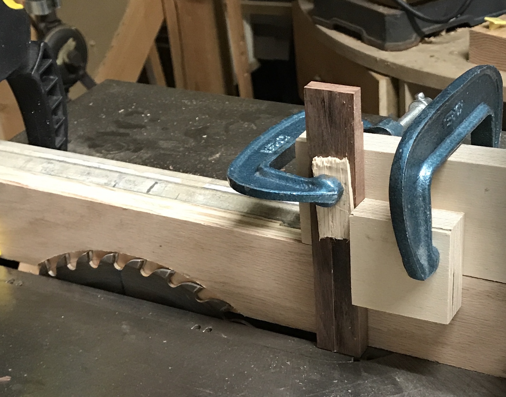
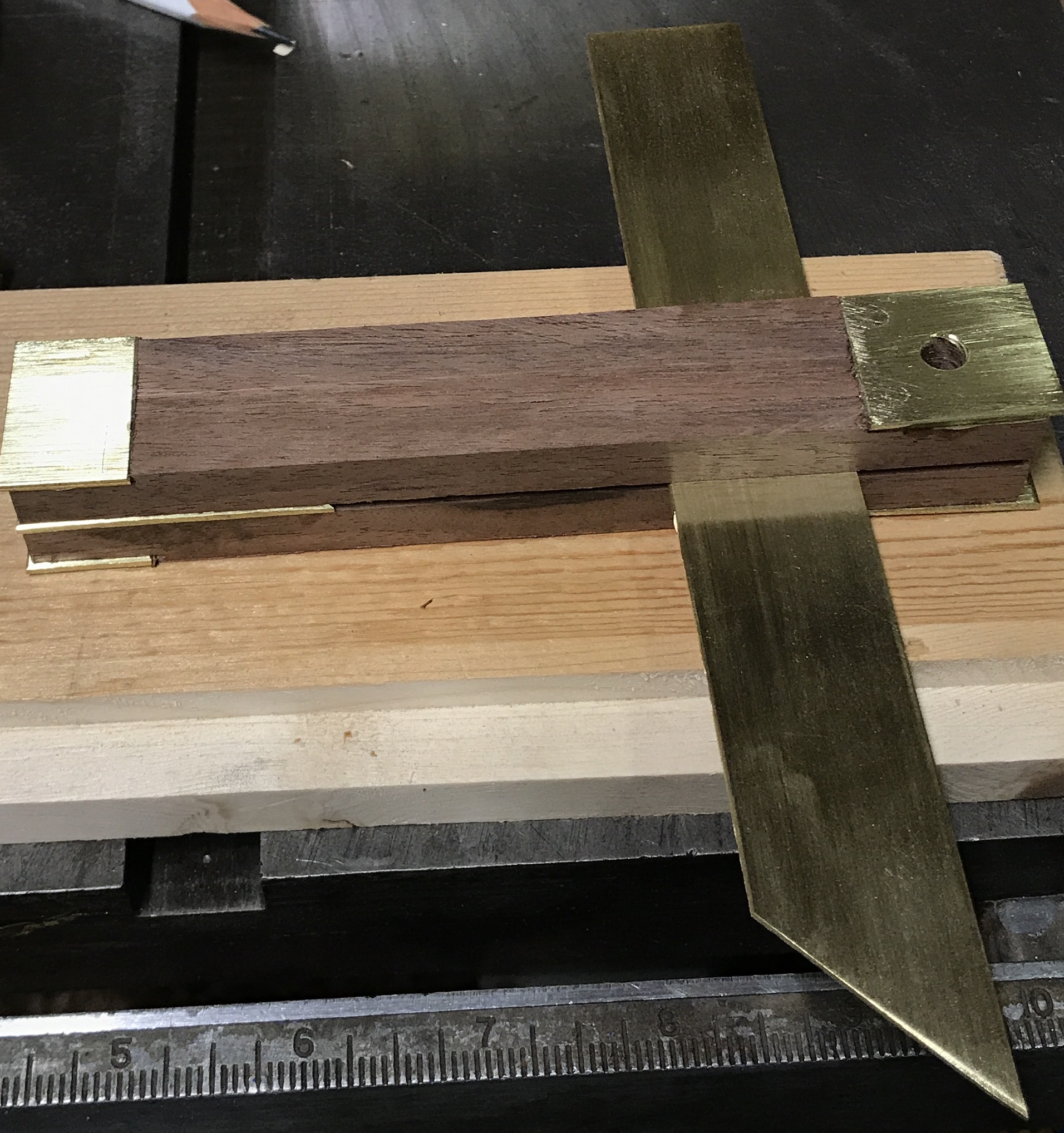
A simple jig was used to cut the rabbets for the brass endplates. First a scrap of plywood was clamped to the fence. It was set 1/16" over the the blade and the blade was raised 3/4". Two scraps of wood were clamped together at a 90° angle. The part was clamped to the jig and slid across the top of the auxiliary board with the eventual outside face against the auxiliary board. The picture below shows the jig in place for a pass. Once the height and depth of the blade was tested on a piece of scrap the bottoms of both handle blanks were run across the blade with the jig. The blade was raised to 1" and the top faces of both handle blanks were cut. The second photo shows the handles cut with the brass parts in place.
The pieces of brass were then carefully sanded on their faces with a small jig. The jig was made from a long block of wood. A rabbet was cut in it about 1" wide and 1/16" deep. 150-grit sand paper was glued to the rabbet with double sided tape. The brass parts were then filed on their ends square to their sides by holding the part in the rabbet and filing flush with the end of the jig. The next step is attaching the end plates to the bottom end of the handle. This requires #2-1/4" wood screws. I only have a few 1/2" long screws, too long to be of use. A box of the required screws was ordered from MicroFasteners.
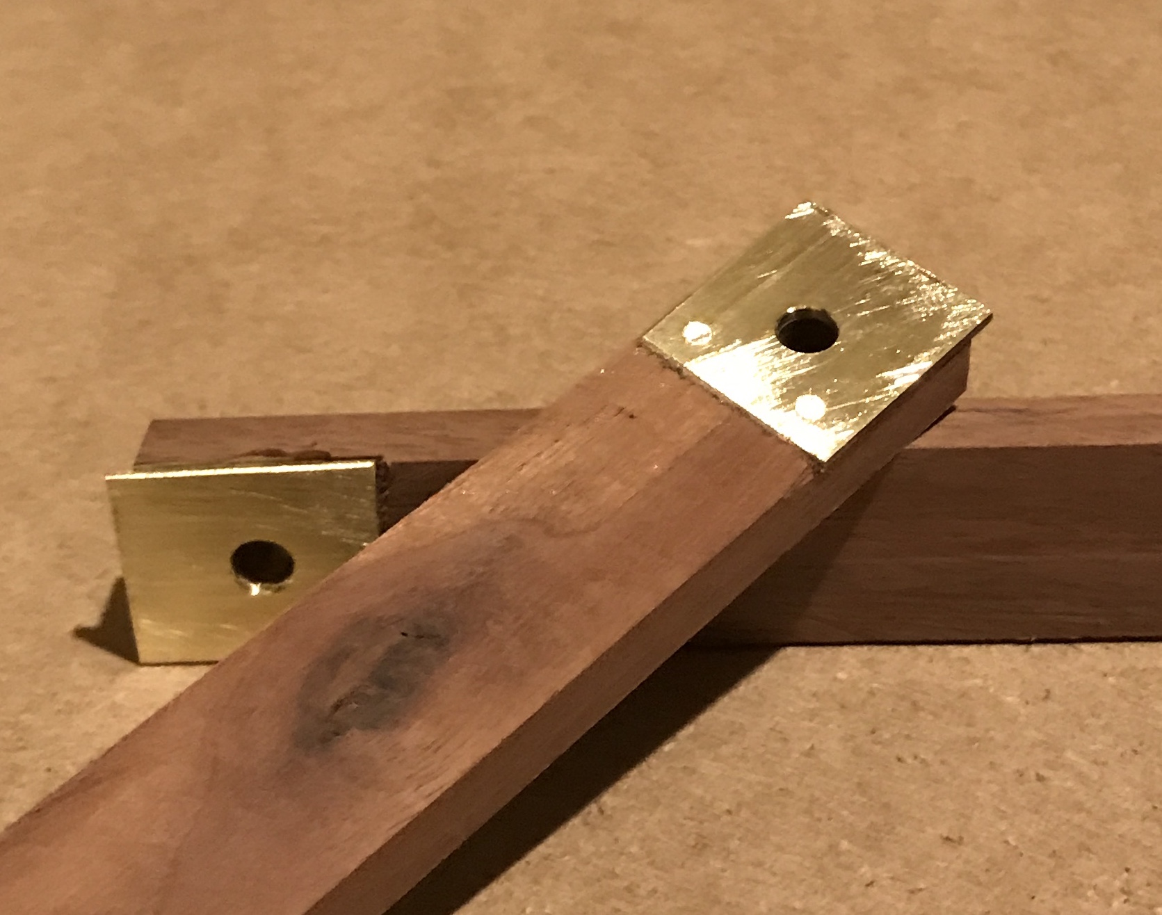
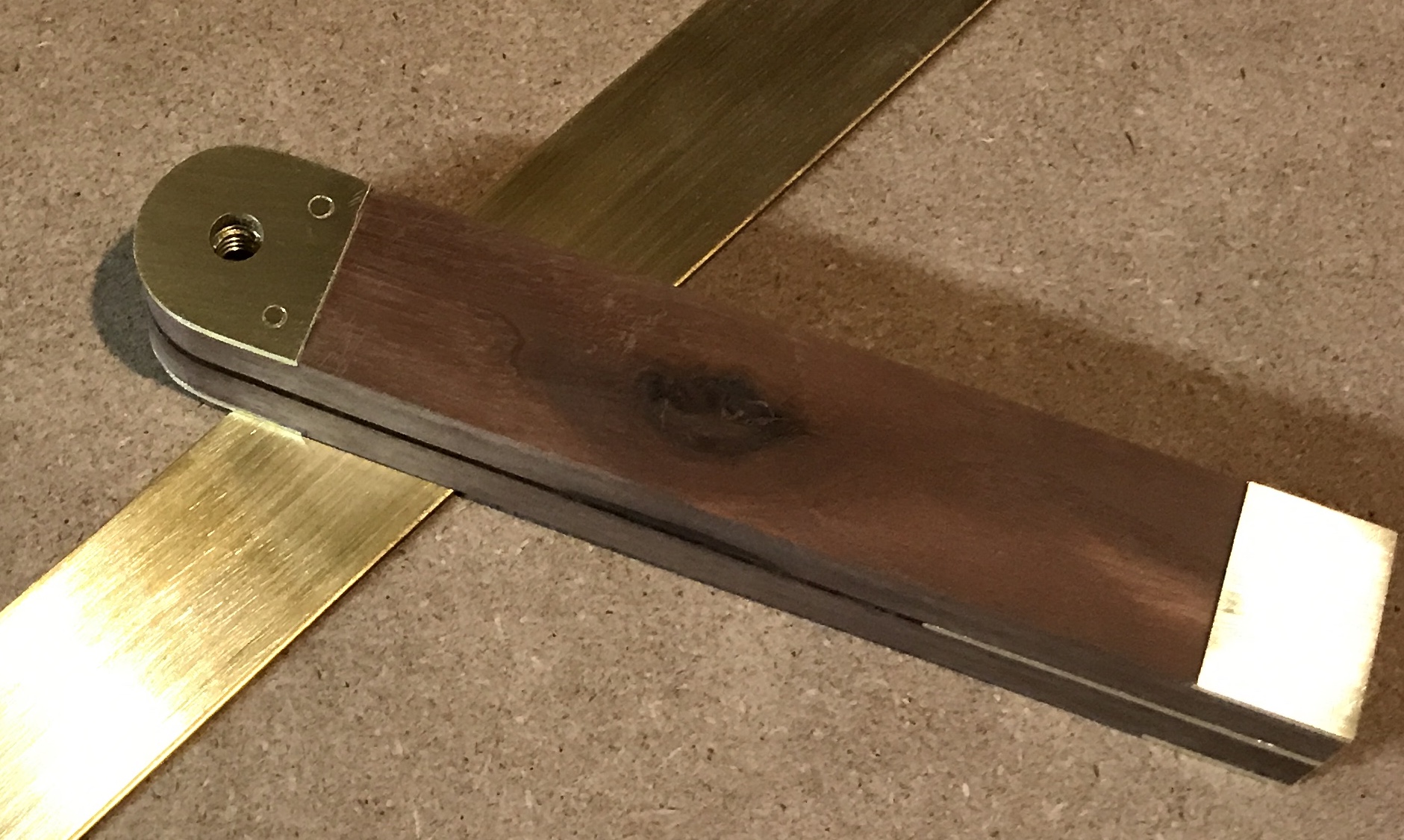
The screws arrived four days later. The top plates and bottom plates were epoxied to the handles and left to dry overnight. The top plates were drilled in two corners each, 3/16" in from both sides, to accept the #2-1/4" screws. The brass plates were chamfered so that the screws when tight were not flush. The slot was completely above the brass plate. The screw heads were filed off as can be seen in the picture below. A 1/4" hole was drilled through both clamped plates centered side to side and 1/2" from the brass wood joint.
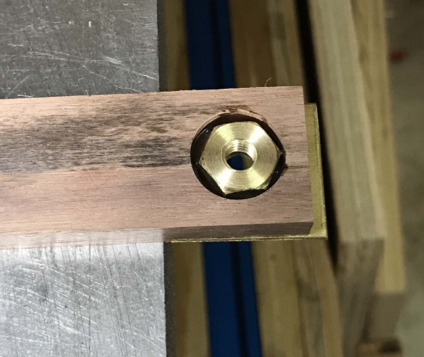
One of the top handles holds a nut for the 1/4-20 bolt through the handle. A handle was drilled with a 5/8" Forstner bit 1/4" deep. The nut was made from a scrap of brass hex. The brass was faced and drilled for a 1/4-20 tap. The part was threaded through and then parted off. Both faces were heavily chamfered. The resulting nut is 9/16" from corner to corner. The nut was epoxied into the hole. The bolt was used to ensure concentricity between the nut and the 1/4" hole. The photo below shows the nut and drying epoxy.
The spacer with the 45° blade stop was coated on one side with epoxy. The spacer was pressed into place on one handle half. Epoxy was put on the other side of the spacer and the second handle half was aligned on top of it. The blade was used to separate the tops of the handle halves. The handle halves were clamped at both ends and the epoxy was allowed to dry.
The next two steps are riveting the bottom end and rounding over the top. To this end a 1" diameter rod of steel was used to put a pencil line on the top for rounding over. The locations for two rivet holes were marked in the bottom, 1/4" in from the sides and centered. These marks were punched and then drilled with a #30 (0.128") drill as the 1/8" brass rod is 0.127" diameter. The holes were chamfered. Two 1" lengths of rod were cut and deburred.
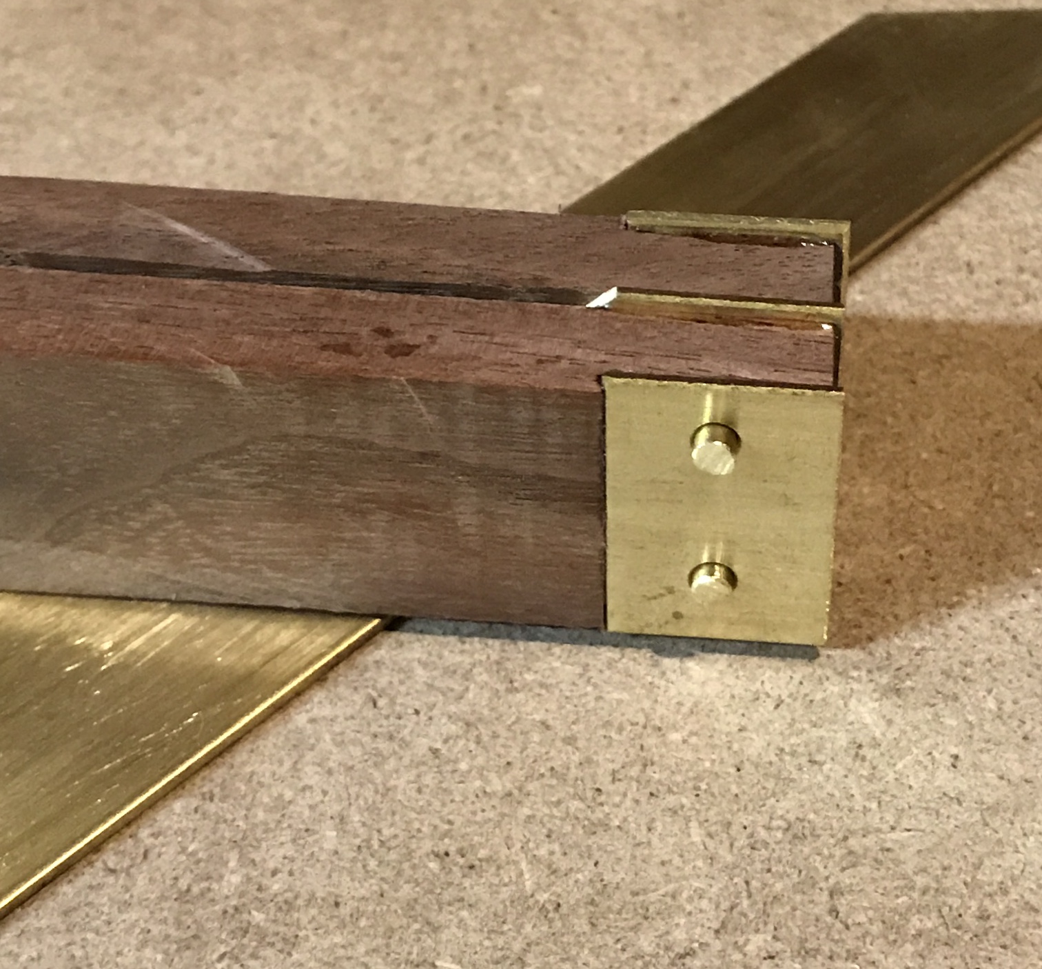
The rivets were put in the holes and peened with the ball peen hammer on a steel plate. The rivet heads were filed flush with the brass plates. Sanded the top end to the line drawn above. The bulk of material was removed with the disk sander and with the drum sander in the drill press. It was completed with a file. The top and bottom brass parts were a little proud of the wood probably due to the glue. They were filed closer to flush. The handle was sanded all over with 150 grit paper. This stage is shown in the photo below.
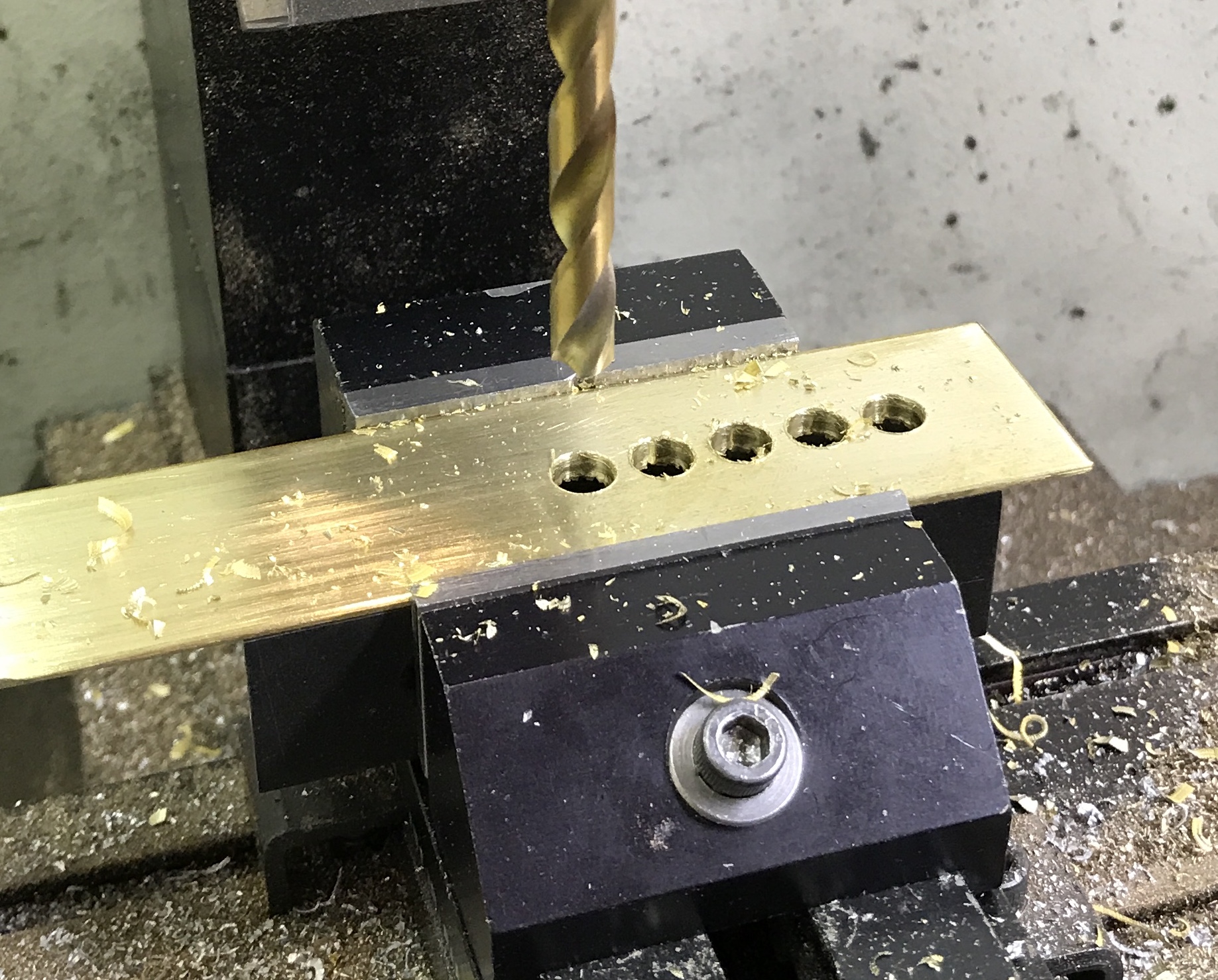
Making the slot was tackled next. The end and side of the blade were located and the spindle moved to 5/8" from the end and centered over the width of the blade. The first hole was center drilled and then drilled through with a 1/4" drill. The table was moved 0.333" and the second hole was drilled in the same fashion. Nine holes were drilled in a line. A 5/32" end mill was used to open the slot. First the tool was set to a 0.020" depth and a pass was made down the center. This was repeated twice to open the center of the slot. The tool was then advanced to the side 0.047" in 0.020" increments. Two were regular milling and the last 0.007" was done climb milling. A photo of the chain drilling is included below.
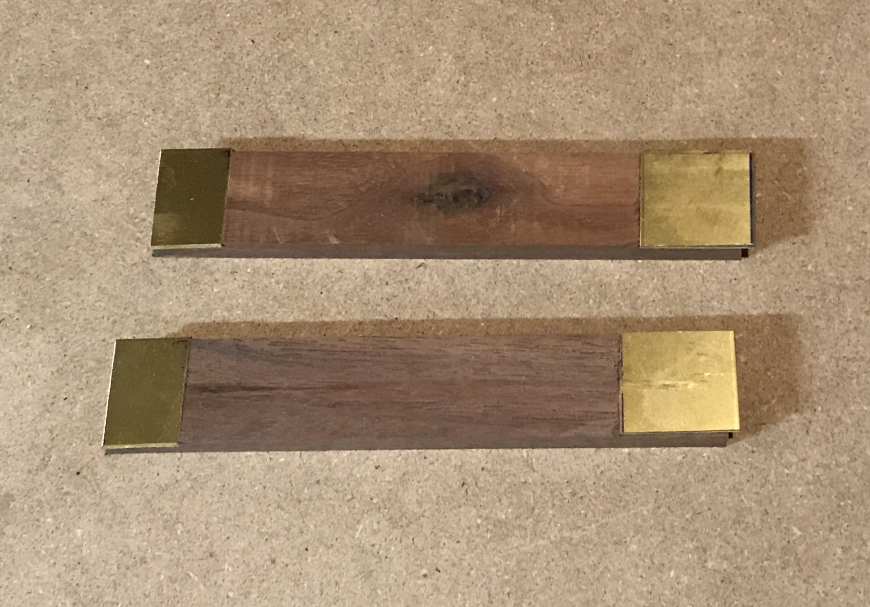
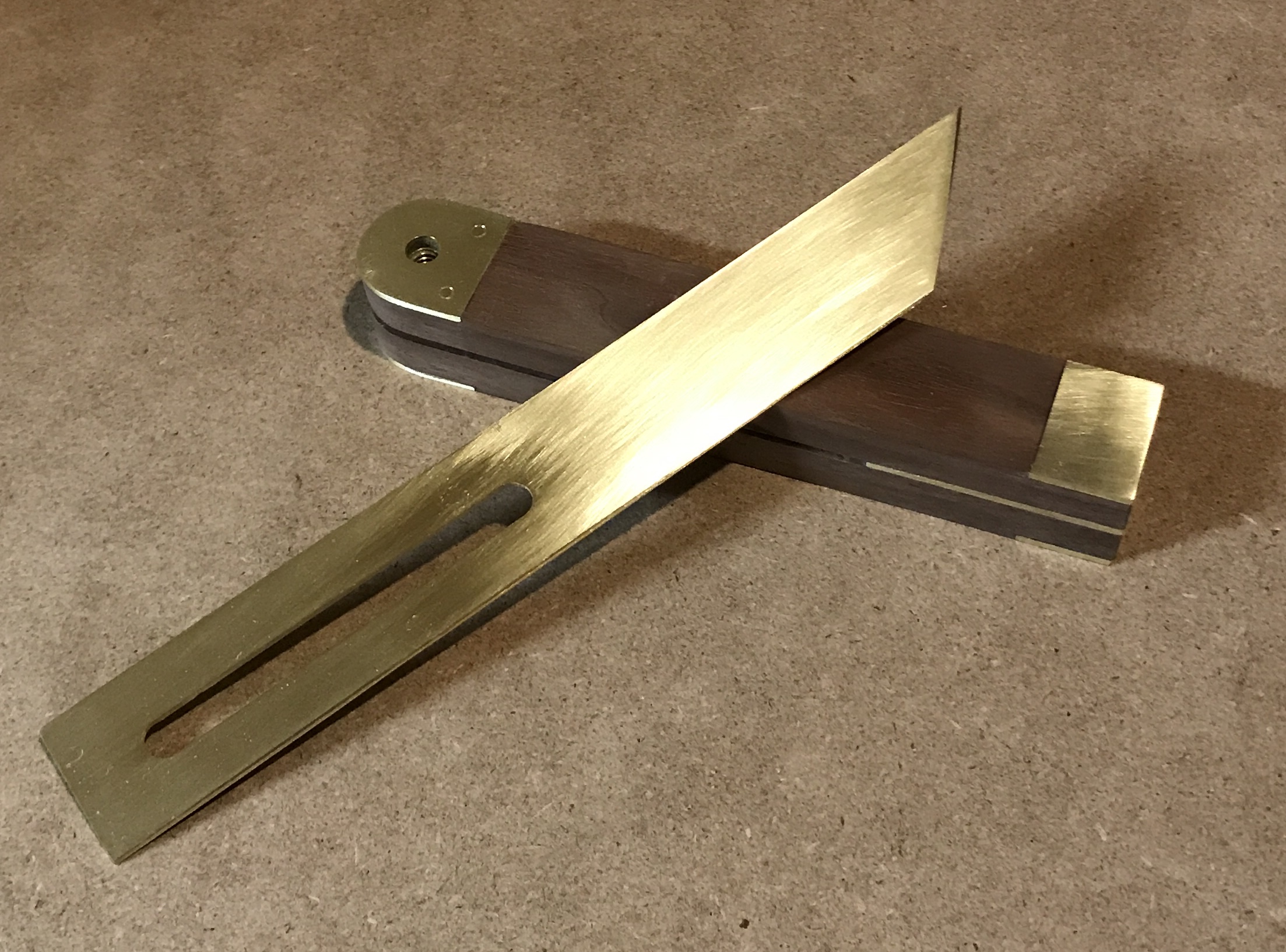
The burrs were removed with a file and the blade was then resanded with 150 grit paper. Both the blade and the handle were sanded successively with 220, 320 and 400 grit paper. The blade and the brass ends of the handle were further sanded with 600 grit paper and then with #0000 steel wool. This left a nice soft luster. The two parts are shown in the photo below.
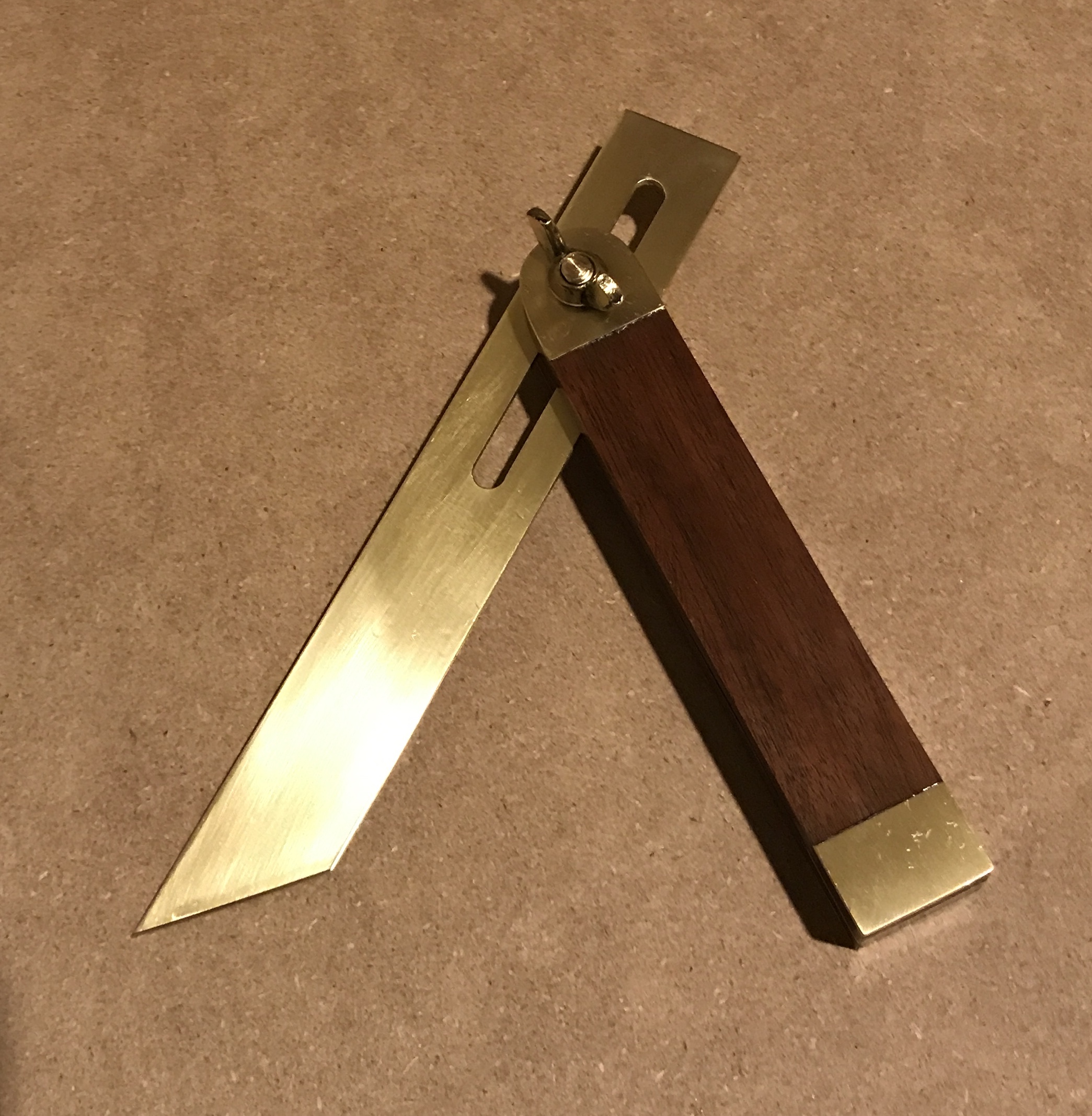
The screw was cut to length and cleaned up in the lathe. The head of the screw was buffed with the steel wool. The brass wingnut was polished. The almost complete bevel gauge is shown below.
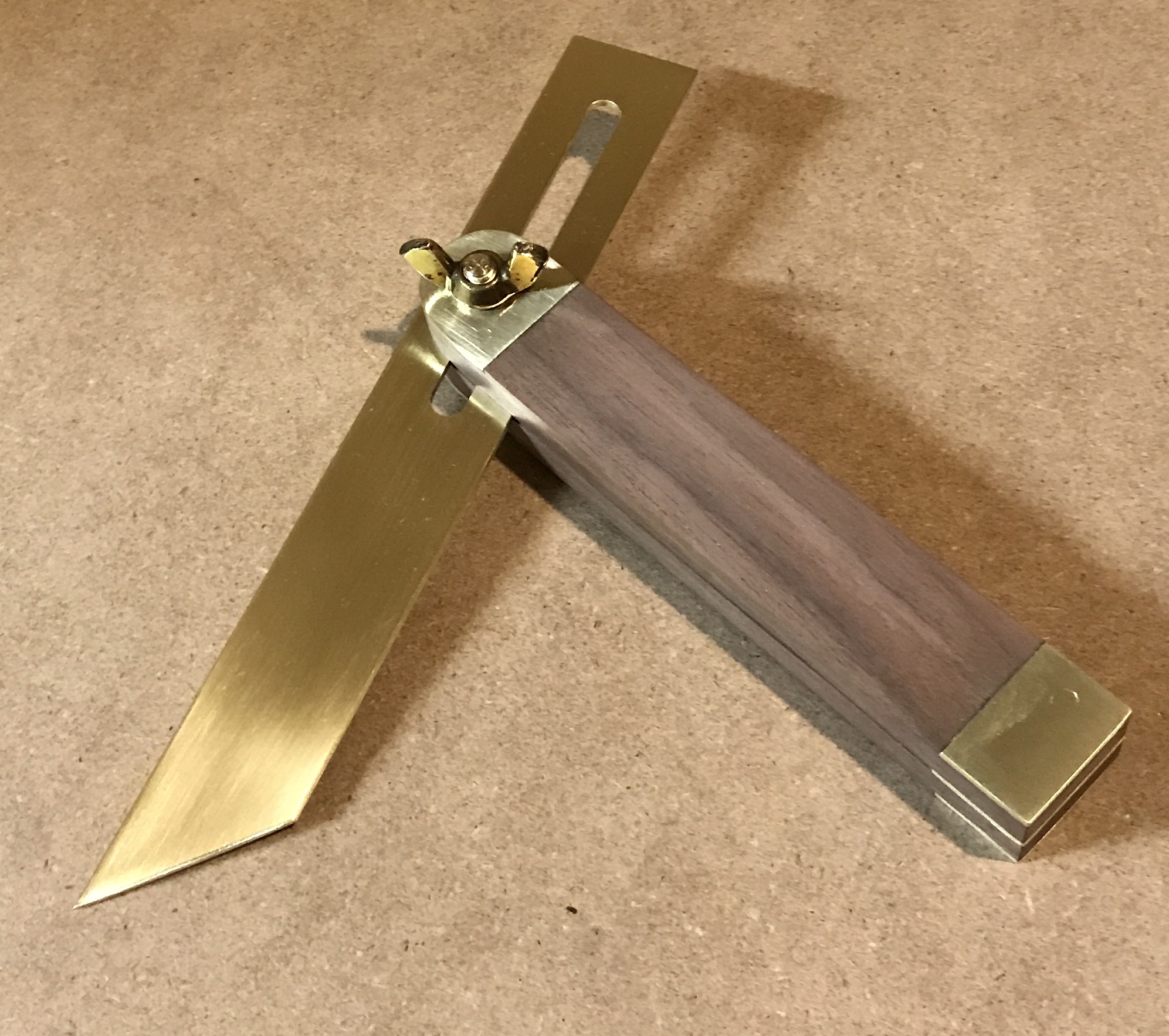
Put a coat of tung oil on the handle, while it was suspended by the screw. The tung oil was applied to both the wood and the brass. The blade was washed and rinsed. Then it was wiped with isopropyl alcohol. A coat of the brass varnish was applied. The varnish was also applied to the wingnut. A second coat of the brass varnish was applied an hour later. A second coat of tung oil was applied to the handle 24 hours later. The completed sliding bevel gauge is show below.